Rope Rescue Equipment (Textiles)
Ropes
Most of the ropes used in LAMRT rope rescue activities are Marlow LSK polyamide low stretch ropes of 11mm diameter with a breaking strain of @35.3 kN and an elongation of @2.4%. The only exceptions to this are a lead climbing rope included within the Advanced Crag kit and the 30m long 9mm diameter ropes for use as ‘confidence ropes’ on steep ground or scrambling routes.
Low stretch ropes are designed to have high strength and minimal extension. The benefits of these properties include:
· Minimal movement of the belay focal points
· Maximum hauling efficiency
· Less bounce when hauling or lowering
· Reduced elongation in a failure and therefore reduced risk of impacting objects
Drawbacks of Low Stretch Ropes include:
· Minimal shock adsorption resulting in the potential for very high loads and fall factors
· Low Stretch Ropes must not be used where there is the possibility of a fall on to a slack rope e.g. when lead climbing. In this situation, a static rope would arrest the fall very rapidly resulting in unacceptably high forces being transmitted to the falling climber and the belay system.
Dynamic ropes are designed to stretch to absorb energy and to minimise the impact on the falling climber. Dynamic ropes are not suitable for most rope rescue situations as the stretch in the rope causes excessive movement of the master points, increases the risk of impacting objects, and reduces the efficiency of hauling systems.
The condition of all ropes must be inspected before, during and after every use. You should avoid standing on ropes and any significant dirt must be washed off after the session. Ropes must be dried after use and stored in the bags provided. Ropes must be stored away from oils, acid, alkali, bodily fluids, UV light and excessive temperatures.
LAMRT low stretch ropes are colour-coded to aid identification. Ropes can be used in any part of the system however the preferred configuration is:
· Black 50m ropes for set up and building the main belay focal points for the MPDs. (X2)
· 50m and 100m Red and Blue Main Lines.
· A set of white 200m ropes are available for very long lowers or guiding lines e.g. Pavey Ark, Gimmer Crag, Bowfell Buttress. Note these ropes are not kept in the vehicles and need to be collected from the equipment store prior to leaving the base.
Slings

LAMRT’s slings are 8mm and 11mm Dyneema@ sewn slings in 120mm, 240mm and 400mm lengths, and they are all rated at 22 kN.
Dyneema@ is light, strong and has good abrasion resistance however has almost no stretch, hence shock-loading must be avoided at all cost. Sharp edges must be avoided. Ropes must not be threaded directly through slings, and slings must be protected from friction caused by ropes moving across them.
How slings are rigged has a substantial impact on strength. Where possible, knotting or larks footing of slings should be avoided. Joining of slings, e.g. when extending a belay, must be done using a self- locking carabiner.

Prusik Loops

The standard rigging and hauling system uses 8mm sewn Prusik loops with a breaking strain of 16 kN. Prusik loops are used for both personal fall protection and in combination with pulley blocks to create hauling systems. Prusik loops are preferred to toothed rope clamps as they allow slippage at high loads and cause less damage to the sheath of the rope. They are light and can also be used as slings if required.
Rope Rescue Equipment (Metallic)
Carabiners
The carabiners used in the rope rigging system are self-locking and require at least three motions to open the gate. This guards against accidental opening of the gate, as this greatly reduces the strength of the carabiner.

DMM Boa ‘LockSafe’ Carabiner
Carabiners must be loaded on the long axis, gates must be closed, and cross-loading and three-way loading must be avoided. Carabiners must not be leveraged across hard objects and the gates must face away from the rock.


Loads should be at less than 120 degrees with friction hitches and belay devices attached at the widest end. The control end of an Italian hitch must exit across the back of the carabiner and not the gate. Where multidirectional loading does take place, it must be into the small end of the carabiner.


Metal on metal contact must be avoided
CMC Rescue MPD
(Note ours are grey in color but of similar design)

CMC MPD (LAMRT are grey in colour)
The CMC Rescue Multipurpose Device (MPD) is a lowering device with assisted breaking and progress capture. It is used during lowering and hauling operations. If the operator loses grip of the control handle or in the event of a sudden change in rate or tension on the rope, the MPD will self-lock. The MPD is a toothless camming pulley device which locks the rope without damaging it. During lowering operations, the locking mechanism is released by simultaneously pulling and turning the control handle. The rate of descent is controlled by holding the dead end of the rope which is passed over the V grove in the control horn. The operator must always hold the rope unless the device is locked using the parking brake function. If the device is to be left unattended, it must also be tied off.
The MPD is threaded as follows (first ensuring that the parking brake is in the unlocked position):

Note that the rope must always be passed around the control horn during belaying or lowering.
After loading the MPD, always perform a function check by pulling hard on the load end of the rope. The MPD should lock immediately.

MPD Function Test
The only time that the rope is not passed over the control horn is when the MPD is being used in hauling mode. The photograph below shows the correct method for controlling the rope when lowering.

MPD Lowering Method
The MPD is normally used as one half of a two tensioned belay system. The Two Tension system usually involves use of a red and a blue rope, hence the MPDs are often referred to as the red and the blue MPD.
The reverse side of the MPD has a ‘parking brake’ knob which can be rotated to lock the device.
If the MPD is to be left loaded and unattended, it must be tied off by tying the tail around the loaded rope using a figure-of-eight on the bight.
At least a metre of rope must be left between the knot and the MPD so it can slip in a controlled manner if something happens.

MPD Tied Off. Note there must be at least 1m of rope between the brake side of the MPD and the knot
The MPD is a force limiting device designed to slip at a maximum load of approximately 12 KN. This is less than half of the minimum breaking strain of the rope and is a key part of the overall safety of the Two Tension system.
Pulleys
The Two Tension rescue system has the option to use both single and double pulley blocks. Pulleys can be used to change the direction of a rope, reduce friction at deviations and for mechanical advantage.

These pulleys are rated for rescue loads and when used for mechanical advantage should be rigged as either a 3:1 or a 5:1 system. The first diagram below shows a 3:1 system with progress capture using two rope clamps. In the LAMRT system, the MPD replaces the upper pulley and a prusik loop replaces the lower rope clamp. The advantage of this in our Dual Capability Two Tension rescue system is that the prusik should slip before the maximum system design load is exceeded, reducing the risk of over-tensioning and snapping the lines.

3:1 using rope clamps (Not used by LAMRT)

3:1 using prusik knot
Note that there are many potential reasons why the prusik may not slip, and if this procedure isn’t followed it is possible to overload the system, particularly if using a 5:1 or if there are multiple persons pulling on the rope. If hauling is unduly difficult or suddenly becomes harder, then you must stop and investigate the cause e.g. the stretcher strops are snagged on a rock.
It is also important to check that the MPD rope is NOT round the friction horn and the MPD is not locked. All strands of the pulley system should be moving and under tension. If this is not the case, stop and investigate the cause.
Edge Protection
Ropes under tension are very easy to cut or damage. Any sharp or rough edges must be protected. Fabric rope protectors are suitable for areas of slight light abrasion; however, loaded lines running over rock edges must be protected using hard plastic edge protectors.
These must also be used to prevent ropes cutting into soil or soft edges.In addition to providing edge protection they help reduce friction when hauling.

Edge protectors have a short length of rope and can be fixed to the belay system to prevent them slipping. There are two sizes and they are stored in the Belay sacks.
Nuts & Cams
Where possible, the preferred belays are large immovable features such as large, sound trees, large blocks, or spikes. These are quick to rig and easy to inspect. If these features are not available, the next choice is to place passive protection devices. The black Belay sack and the Advanced Crag sack contain a selection of ‘nuts’. These are placed in cracks to build a belay system.

A selection of DMM nuts of various sizes and design
The loading capacity of the nut is dependent upon the size and type of the nut, the quality of the placement, and the strength of the rock. For example, a small nut placed in soft sandstone rock will hold much less load than the same nut placed in granite.

A good nut placement in solid rock with high contact area
The security and loading capacity of nut placements is very dependent upon contact area. Strong placements will have a good match between the shape and angles of the nut and those of the rock.
The photograph above shows a well-placed small nut. Note however that the crack widens behind the nut and it may have been possible to get an equally good fit with a larger and therefore even stronger nut. The smallest DMM Walnuts have a holding capacity of about 7 kN in good rock. This rises to approximately 12 kN for the larger Walnuts.
Traditional passive nuts, e.g. DMM Walnuts, require a constriction or narrowing crack to make the placement. However, if the only placement available is a near parallel sided crack, then a camming nut like the DMM Torque Nut may be a good choice. The placement of camming nuts is shown in the following diagram.

Correct use of Torque Nuts
If the only available placements are parallel sided cracks, then then the only remaining option is to use a mechanical camming device like the DMM Dragon Cam.
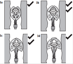
Acceptable cam placements
The above diagrams show good cam placements. Be careful however not to force cams into cracks that are too small as they can become impossible to retrieve. The diagrams below show poor cam size selection and placements. Cams also perform poorly in icy cracks. Also take care that cams are not repeatedly pulled from side to side as they can tend to ‘walk’ into or – more significantly – out of cracks. The holding power of Dragon Cams and Torque Nuts in good placements is around 14 kN.
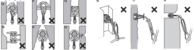
Poor Cam placements
DMM Talon Steep Ground Anchor

Installation of the Talon
LAMRT’s main use of the DMM Talon is to provide additional security when carrying or sledging the stretcher on low-angle terrain when there is a lack of other belays. The Talon is not ideally suited for use in high-angled rescues.
When in use, the Talon must be attended to ensure that it does not ‘creep’ e.g. due to heavy rainfall or vibration. The best way to do this is to stand on the Talon.

Maintain angles <90 Degrees
Note that if a hammer is not available, the Talon can be stamped into the ground.
Petzl Reverso

The Petzl Reverso is a multifunctional belay / rappel device suitable for belaying one or two climbers from above or a single climber from below. LAMRT use the Reverso for belaying in a scrambling situation, as a personal abseil device or in exceptional circumstances for belaying a lead climber.

Treading the Reverso
If belaying a single climber from below the Reverso will normally be clipped directly in to the belay loop on the belayers harness using an autolocking or screw gate carabiner. The rope should be orientated with the brake side passing over the braking groves with the gate of the locking carabiner facing the braking hand.
When abseiling or belaying the brake side of the rope should be held firmly at all times with the brake hand behind the device and a minimum of 8” away from it (to prevent the hand being pulled in to the Reverso in the event of a fall). This is the normal “ready” position as shown above.
If belaying from above it can be difficult to maintain the brake hand sufficiently behind the device to provide maximum braking.
In this case it is preferable to use a alternative top rope belay method e.g. Italian Hitch.
NOTE. BELAYING IS AN IMPORTANT PRACTICAL SKILL NOT COVERED IN THIS MANUAL.
Equipment Inspection & Storage
All equipment is subjected to six-monthly checks by qualified inspectors. In addition to this, team members must conduct their own pre-use and function checks on all equipment e.g. checking that the sling on a camming device is in good condition and that the cams move freely.
Any equipment that may have been damaged in use must be quarantined. Note that damage could be obvious, e.g. a cut in a rope, or less obvious, e.g. a rope used at an RTA which could have been contaminated with vehicle fuel.
All equipment involved in a high-energy event needs to be quarantined until inspected by a qualified person e.g. if an edge transition has gone wrong or there has been a significant fall.
Training Syllabus and Sign Off
LAMRT members are required to maintain a minimum standard of proficiency in rope rescue and have the option of obtaining additional more advanced qualifications.
Competency is assessed by authorised team members and recorded on the individual team members Rope Rescue Skills Log.